Firmware and GUI core functionalities are implemented
As mentioned in the previous blog, the first milestone includes the development of core (minimal) firmware and GUI functionalities.
Firmware implementation
The entirety of the firmware source code created for this milestone can be found in the Firmware/ADFirmware path. Before implementing core functionalities, an important step involved defining a coherent structure for the firmware source code and aligning it with the described firmware architecture. To provide a comprehensive understanding, we will first detail the organization of firmware directories. Subsequently, we will offer a brief overview of the functional blocks integrated into this milestone. Finally, we will guide you through importing, running, and compiling projects within the STM32Cube IDE.
Firmware directory's structure
The complete firmware source code structure is organized as it is presented in Figure 1:

- CM4 – Complete source code that will be run on Cortex M4 core.
- CM7 – Complete source code that will be run on Contex M7 core.
- Common – Startup file directory to booth all cores successfully.
- Drivers – STM32 driver library from the official STM32H7 Cube git repository
- Middleware – Third parties’ libraries common for all cores (for example FreeRTOS, LwIP, etc)
Within each core directory (CM4 and CM7) is implemented code directory organization to correspond to the overall firmware architecture described here. This organization is illustrated in the following figure:
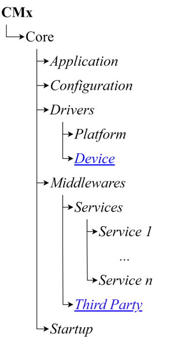
- Application– Contains firmware top-level source code.
- Configuration – Contains all configuration files such as global firmware configuration, LwIP configuration, FreeRTOS configuration
- Drivers – This directory contains two sub-directories: Platform and Device. The platform directory contains thread-safe platform-independent drivers for different peripherals (UART, SPI, I2C) while the Device directory is linked to the Driver’s directory from Figure 1.
- Middlewares– This directory contains two subdirectories: Services and Third party. Each service functionality, that corresponds to the Acquisition device architecture described here, will be implemented within a separate subdirectory. The third-party directory is linked to the Middlewares directory from Figure 1.
Firmware core functionalities
Overall firmware architecture that presents blocks implemented within this milestone is illustrated in Figure 3.
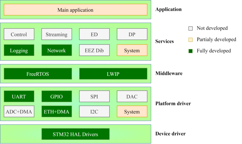
- System Driver– This driver is partially developed. For now, it is in charge of reporting firmware execution status such as errors, link status, and others.
- UART Driver – Thread safe platform-independent wrapper around standard STM UART driver library
- GPIO Driver– Thread safe platform-independent wrapper around standard STM ETH driver library
- ETH+DMA Driver– This directory contains two subdirectories: Services and Third party. Each service functionality, that corresponds to the Acquisition device architecture described here, will be implemented within a separate subdirectory. The third-party directory is linked to the Middlewares directory from Figure 1.
- Logging Service - In charge of packing log messages and sending them over the logging channel. Within current implementation
- Network Service - Monitor link status
- System Service - Create all other services and monitor firmware execution.
Compile and run acquisition device firmware
STM32Cube IDE is used for code development and the source code located on the GitHub repo is completely adapted to simplify project distribution over different machines that run this tool.
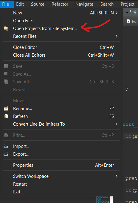
After the complete project is pulled from the project GitHub repo it should be imported within STM32Cube IDE. This is done by clicking on File-> Open Projects From Filesystem as shown in Figure 4.
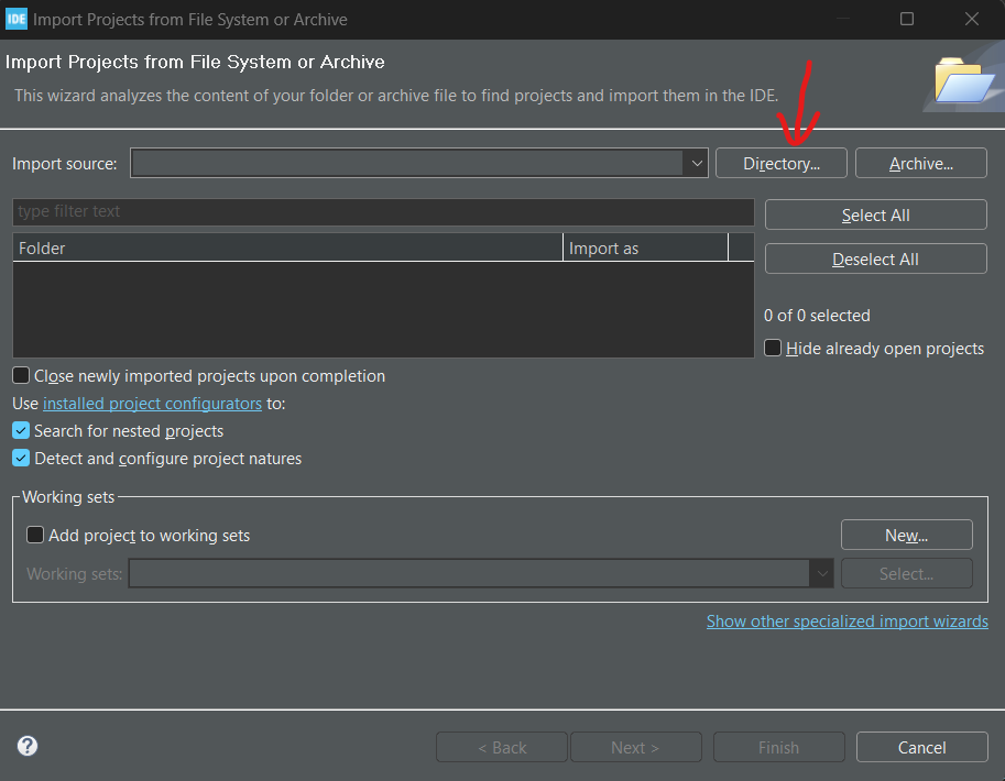
After selecting this option, the dialog presented in Figure 5 is opened. Within this dialog, we should press the Directory button and configure the ADFirmware directory path.
When the project is successfully imported, it should be available within the STM32Cube IDE project explorer subwindow located on the left side as it is presented in Figure 6.
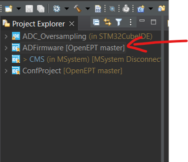
After the project is successfully imported it is ready to be compiled and run on NUCLEO -H747ZI2 platform. If you have any issues during the compilation process, contact our development team.
GUI implementation
The complete GUI source code created for this milestone can be found in the GUI/OpenEPT path. A current version of the GUI application implements only fronted elements with empty backend callback functions. These functions will be implemented within the future milestones. Through this blog, we will first present several windows and dialogs implemented as part of the GUI front end. Subsequently, we will guide you through importing, compiling, and running projects within the Qt Creator.
GUI Windows
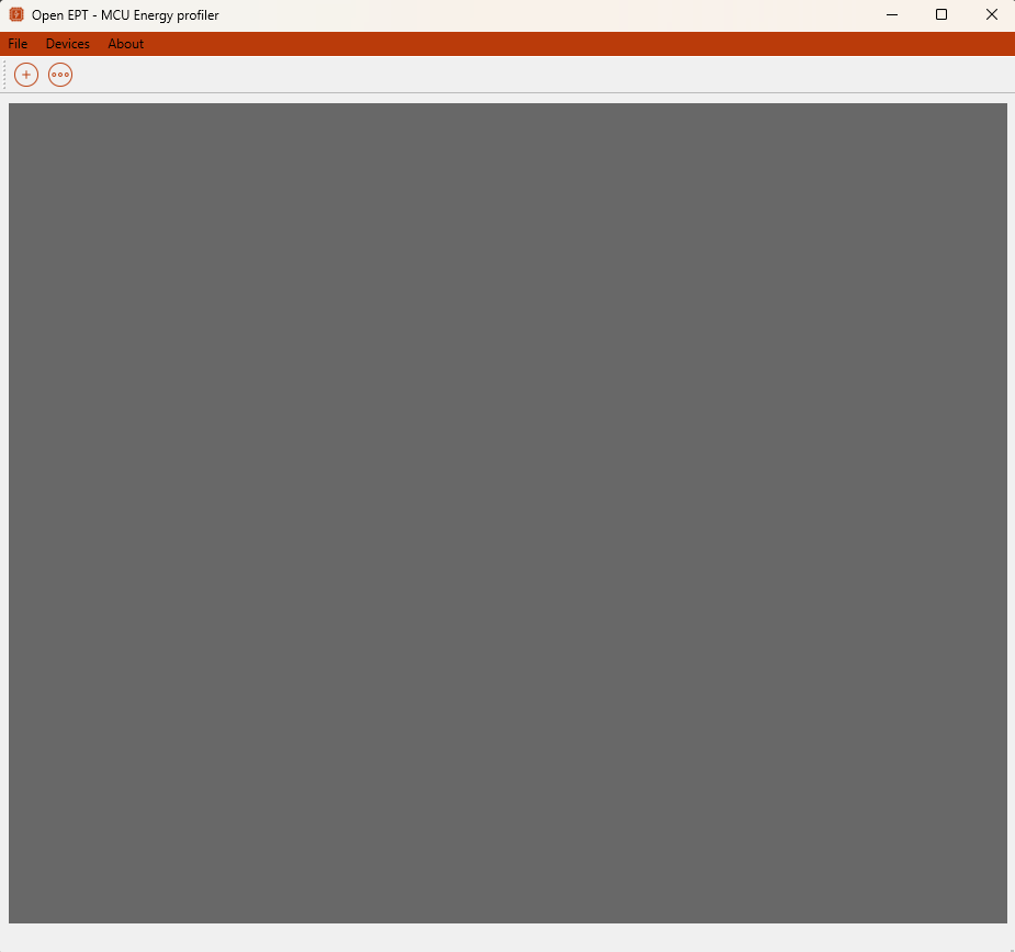
The first application version integrates several windows. After the application is started, the main window is opened as presented in Figure 7.
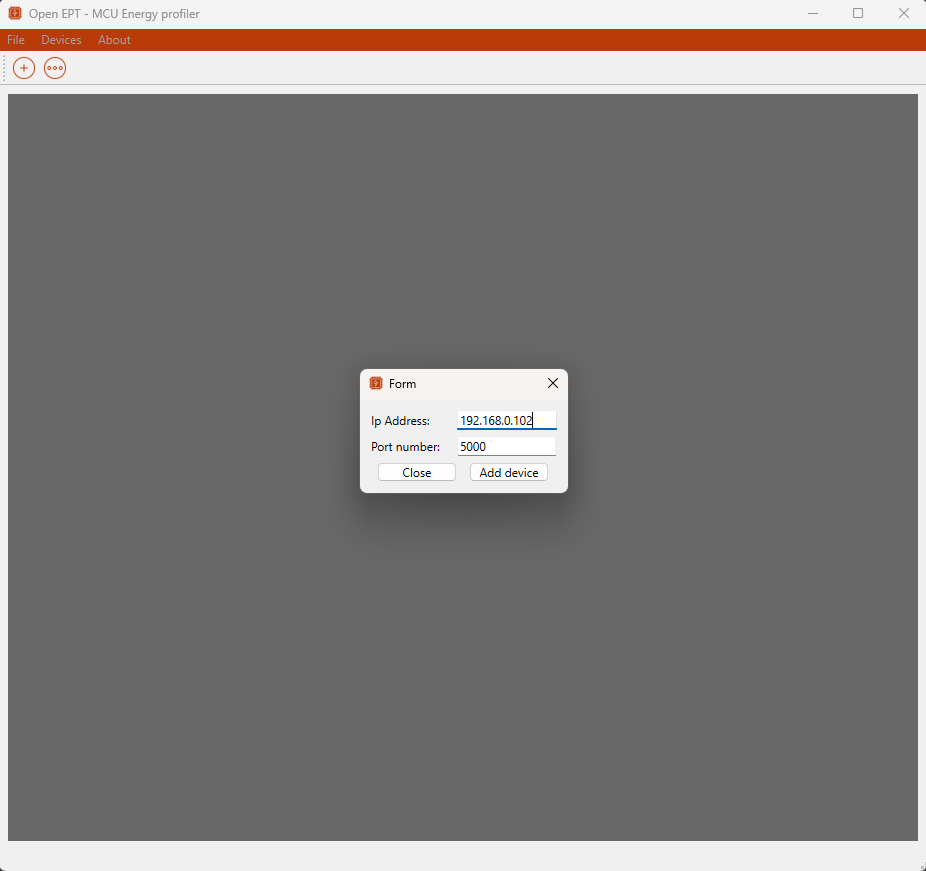
Within the Main application window, from the Menu bar is possible to select Devices->Add device after which a pop-up window is displayed and the user should enter the Acquisition device IP address and port. This Add device dialog is presented in Figure 8.
When the user enters the Device IP address, the Device window appears and presents the device's relevant information. This window is logically divided into three layouts:
- Measurements plot layout (Current, Voltage, Consumption)
- Device status and control
- Application log window
The device window layout is presented in Figure 9.

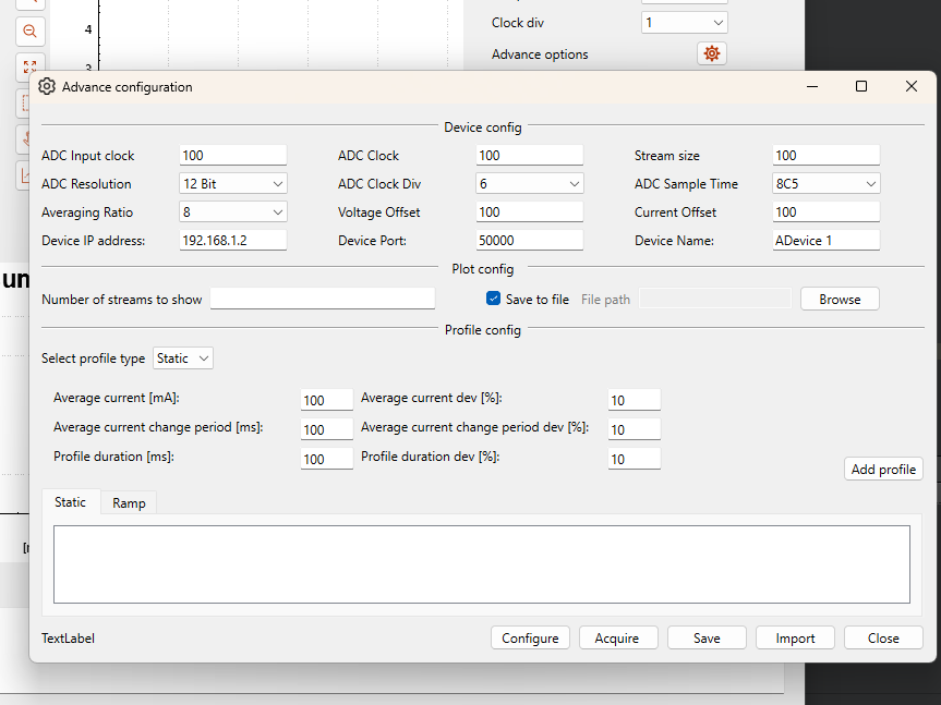
The device window presents only basic device configuration. However, it is possible to open the Advance configuration window which provides wider configuration options. This window layout is presented in Figure 10.
Compile and run application
In order to run OpenEPT application installation of Qt software is needed. Download of Qt is available in this website -
NOTE: in order for Compiler to be compatible with Qt version, MSVC2019 needs to be installed on PC. This can be downloaded here.
Version of Qt is 6.2.4 and all additional libraries are following:
|--Qt
|--Qt 6.2.4
| |-- MSCV 2019 64-bit
| |-- Sources
| |-- Additional libraries
| | |--Qt charts
| | |--Qt image formats
| | |--Qt websockets
| |--Qt Debug Information Files
|--Developer and Designer Tools
|--Qt Creator 12.0.0
|--Qt Creator 12.0.0 CDB Debugger Support
|--Debugger Tools for Windows
|--Qt Installer Framework 4.6
|--CMake 3.27.7
|--Qt Maintenance Tool
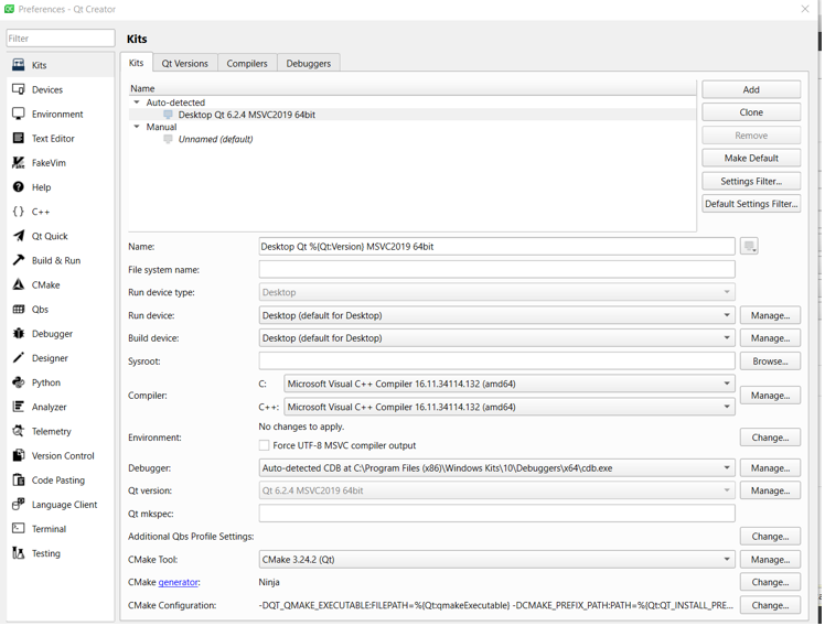
Every prerequisite is listed in Figure 11:

Project setup is done in Qt Creator in upper toolbar we have Edit -> Preferences and the setup should look like this (for this MSVC2019 is required):